|
|
4 years ago | |
|---|---|---|
| case | 4 years ago | |
| components | 4 years ago | |
| doc | 4 years ago | |
| main | 4 years ago | |
| pcb/kicad | 4 years ago | |
| third-party/milligram | 4 years ago | |
| .gitignore | 4 years ago | |
| CMakeLists.txt | 4 years ago | |
| COPYRIGHT.txt | 4 years ago | |
| LICENSE.txt | 4 years ago | |
| README.md | 4 years ago | |
| sdkconfig | 4 years ago | |
README.md
MqTrigger

- Overview
1.1. Components
1.2. Features - How it works
2.1. Pinout
2.2. Message format
2.3. Testing with mosquitto - Building
3.1. ESP IDF installation
3.2. Compilation - Flashing
4.1. Flash using idf.py
4.2. Flash using esptool - Licensing
Overview
MqTrigger is a simple, multi-channel switch controller with MQTT(S) and HTTP API. The project arose from the need to drive separate boards of encoded remote controllers (433 an 868MHz gate, garage, alarm system remotes) as well as general-purpose 230V relays.
Components
- software
- double-sided printed circuit board
- 3D printed modular casing
Features
- switch control via local network or over the Internet using a smartphone app or command line
- local WEB configuration panel
- simple REST API for triggering and configuration
- built-in MQTT client with optional encryption (TLS) and/or user authentication
- device monitoring (heartbeats)
- input voltage 4.5-22V (depends on the regulator used)
- controlled current 35V/50mA (depends on transoptors/transistors used)
- time synchronization (SNTP) and time zone configuration
- status signalling via RGB LED
- USB software update
- power saving mode
- cooperation with popular applications for Android and iOS (such as MQTT Dashboard)
- reboot scheduling
- static and dynamic IP configuration
- DNS configuration
- access point and WiFi station mode
- service mode and factory settings reset button
How it works
This is a standard optocoupler setup driven by ESP32 uC. You can hack into between the button pins of the remote control board with its own power supply, or use the extra power port and jumpers on the MqTrigger board. Any other circuit with GPIO or high voltage relays will also work. By design, the application switches the states of the outputs temporarily, but converting an output to e.g. PWM signal should not be a problem.
Pinout
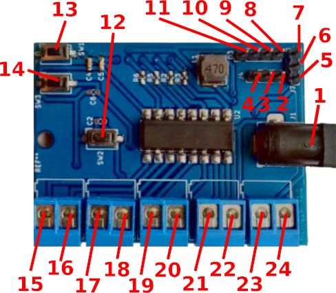
- DC power supply (4.5-22V)
- UC UART GND
- uC UART TXD pin
- uC UART RXD pin
- input voltage pin
- configurable pin
- voltage pin 3.3V
- blue LED pin
- green LED pin
- cathode LED
- red LED pin
- programming button
- reset button
- service button
- emitter of trigger 3
- collector of trigger 3
- emitter of trigger 2
- collector of trigger 2
- emitter of trigger 1
- collector of trigger 1
- emitter of trigger 0
- collector of trigger 0
- GND
- configurable pin output
Message format
Both HTTP (POST) requests and published MQTT messages have the same format: <command> <arg1> <arg2> ... <argN>.
Switch state altering commands:
trigger <n> <duration ms> - trigger the nth switch for a given time (milliseconds);
on <n> - turn on the nth switch;
off <n> - turn off the nth switch;
Additionally, the /app and /sys URIs accept the string in the POST request as option1=value1&optionN=valueN. To change device settings via MQTT, use the setapp <options string> or setsys <options string> message format. To learn more about the keys and values of application and system settings, see the components/software/src/*Api.c files.
MQTT message examples:
trigger 0 2000 - turn on switch 0 for 2 seconds;
off 3 - turn off switch 3;
setsys wstatic=0&dns=1.1.1.1 - update system settings (here: use DHCP and set DNS server address);
setapp mqtls=0&mqhb=mqt/test/hb - update application settings (here: do not use TLS, set the heartbeat topic)
Testing with mosquitto
mosquitto_pub -t mqt/test/api -h my-mqtt-server.net -p 8883 --cafile ./ca.crt -i client_name -u testuser -P testpassword -m "trigger 0 3000"
Service mode
Press the service and the reset button, then release both buttons to boot into service mode. Now there should be unprotected (no password) access point available as mqt-<mac> SSID. Web control panel will be available under 192.168.4.1 IP address. Next boot will exit the service mode.
Factory reset
Press the service and the reset button, then release reset button and keep holding the service button for at least 10 seconds. Default settings will be restored and the device will boot into the service mode.
Building
ESP IDF installation
Clone esp-idf project:
cd ~/src
git clone --recursive --branch v4.2.2 --depth 1 https://github.com/espressif/esp-idf.git
Install esp-idf:
cd ~/src/esp-idf
bash ./install.sh
Compilation
Setup the environment:
cd mqtrigger
source ~/src/esp-idf/export.sh
OPTIONAL: Change project settings:
idf.py menuconfig
Run idf.py to build the project:
idf.py build
Flashing
Press boot + reset button before flashing.
Flash using idf.py
If the SDK is installed and the environment is set up, then the binary can be uploaded just after the build:
idf.py -p /dev/ttyUSB0 flash
Flash using esptool
esptool -p /dev/ttyUSB0 -b 460800 \
  --before default_reset --after hard_reset \
  --chip esp32  write_flash --flash_mode dio --flash_size detect --flash_freq 40m \
  0x1000 bootloader/bootloader.bin \
  0x8000 partition_table/partition-table.bin \
  0x10000 mqtrigger.bin
Licensing
Distributed under the MIT License.
See accompanying file LICENSE.txt for the full license.